Your First CNC Milling Toolpaths in Fusion 360
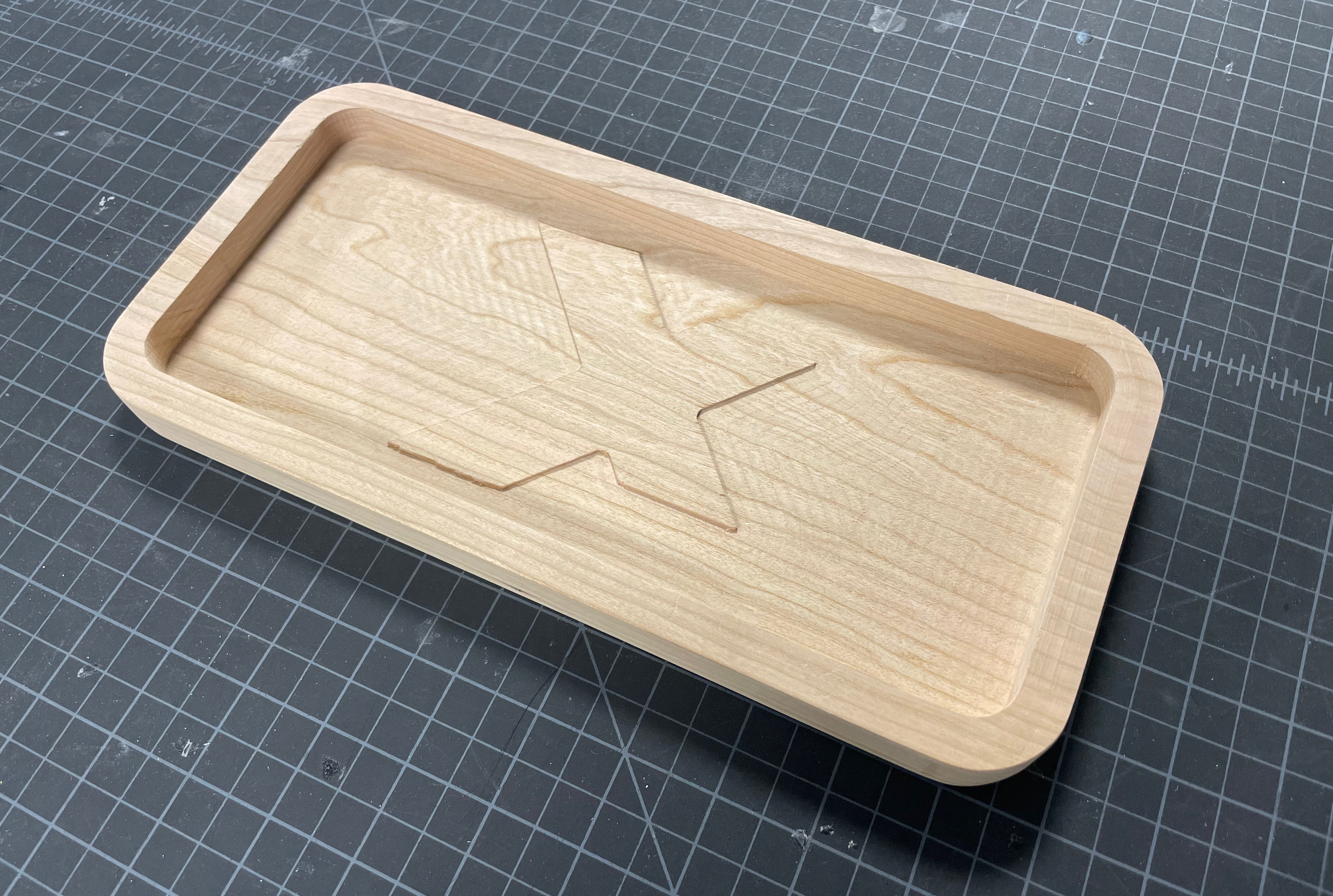
We’ll be designing a desk tray to demo some of the most usefull CNC toolpath types in Fusion 360.
Download the Design
In order to teach about toolpaths, we all need to work on a consistent base. Download the design here and open it with Fusion 360. As long as the outer dimensions stay the same, we encourage you to customize the design to fit your desk.
Prepare the Toolpaths
When you’re happy with your design, press the “DESIGN” button in the upper left corner and select “MANUFACTURE”. This will bring you to the Fusion 360 menu with tools to aid in fabricating your designs.
Setup
Make sure the document units are set to inches. In the project browser, right click on “Setups” and select “New Setup”.
In the Setup menu, in the Setup tab, under “Model”, select “Body” and make sure your desk tray model is selected.
Change to the Stock tab, in the “Mode” menu, select “Fixed size box”. Enter in the dimensions of the stock (12” x 6” x 0.75”) and make sure that all “Model Position” menus are set to “Center”.
Move the origin of the stock to the bottom left corner of the stock. This spot will be at (0,0,0) on the machine. This will make it easier to align what happens on the machine with what’s designed in the computer.
Press OK, if you ever exit the setup menu before you’re done, right click the setup in the project browser and select “edit”
2D Pocket
The first toolpath we will use is called a “pocket”. This is useful for removing an enclosed section of material without cutting all the way through. In the top toolbar, press the “2D” dropdown menu and select “2D Pocket”.
First, change to the “Geometry” tab of the 2D pocket menu. In the Geometry section, press “Select” and click on the main inner surface of the desk tray.
Move back to the “Tool” tab of the 2D pocket menu. In the “Tool” section, press the button that says “Select”. Expand the “Fusion 360 Library” meny on the left side of the pop-up menu. Select the “Milling Tools (Inch)” section. Choose the router bit that says “(1/4” Flat Endmill)”.
In the same Tool tab, in the “Feed & Speed” section, change the “Cutting Feedrate” to 80in/min.
In the “Passes” tab, uncheck “Stock to Leave” and check “Multiple Depths”. Set the “Maximum Roughing Stepdown” to 1/2 of the router bits diameter (in this case: 0.125”).
You should not have to edit anything in the “Heights” or “Linking” tabs.
2D Face
The next toolpath we will use is called a “facing” path. This toolpath is not necessary for most CNC milling projects, but is usefull for cleaning up a flat, top surface of a design or planing large pieces of stock. In the 2D dropdown menu, select “Face”.
In the geometry tab of the Face menu, select the outer contour of the raised ‘X’ design.
In the tool tab, Fusion should have remembered your tool selection from earlier. Double check the type and cutting feedrate just to make sure.
The “Heights” tab will determine the cutting depth of this operation. In the Heights tab, in the “Bottom Hieght” section, change the reference plane under “From” to “Origin (absolute)”. Set the height to 0.3”.
In the “Passes” tab, check the “Multiple Depths” box and set the maximum stepdown to 0.125”.
This operation is potentially dangerous when done inside of higher walls within the design. It is appropriate here because the area being cut is completely surrounded by areas lower than the face. If you would like a sunked design, use another 2D pocket pass.
2D Contour
The last toolpath we will use is a “2D Contour”. Select it from the same 2D dropdown menu.
In the geometry section of the geometry tab, where it says “Contour Selection”, press “Select” and click on the bottom exterior line of the overall design. The red arrow should be on the outside of the line.
Double check the settings in the tool tab, and select Multiple Depths in the Passes tab. Set the max roughing stepdown to 0.125”.
Press OK. This type of step is typically done last because it will seperate the design from the rest of the stock. This has the potential to decrease the stiffness of the piece. If this piece were to move even a little, it would decrease the accuracy of the inner cuts. It is best to work from the inside out.
Finalizing and Exporting
Once you have finished programming all of your toolpaths, you need to simulate and export the code for the CNC router.
Simulation
Right click the setup in the project browser and select “Simulate”. Press play to watch the simulation of your cuts. Watch the entire process to make sure there is nothing unexpected. You can adjust the speed to go through it faster.
Check the bottom timeline for any warnings or errors. If there are any red or yellow marks that you cannot resolve, ask a crew member for help before exporting for the machine.
The last thing you should check here is the statistics tab of the simulation window. The machine time should be something reasonable. The format is hours : minutes : seconds. If it shows something far above what you expect, check your toolpath settings again before asking for help.
Exporting
Once everything looks ready to cut, you will need to export the CNC code for the router. Right click on the setup and press “Post Process”. In the pop-up window, press the drop-down menu next to “Post” and select “Choose from Library”, this is where you will select the type of machine you will be cutting on. For our shop choose “ShopBot OpenSBP / shopbot” You also need to change the name of your file here. It is best practice to include the size of the router bit youre using e.g. “1-4b_desk_tray”. Press “Post” and refer to this tutorial for setting up the machine to cut.